Sunday, May 24, 2009

How to Network Your Computers

It's not surprising that home networking is hot: Nearly 70 percent of U.S. households with broadband connections have more than one computer. If you want all your computers to share one Internet connection, this information will help you make the right choices.
  • Learn the jargon
  • Step 1
    A router relays data between your broadband Internet connection and your individual computers.
  • Step 2
    A network adapter connects to each computer. It sends data from the computer to the router.
  • Step 3
    An Internet protocol (IP) address is your computer's unique identification on the Internet. When you have a home network, all your computers share one IP address.
  • Step 4
    A print server is a special network adapter that's used to connect a printer to a network. With a print server, several computers can share one printer.

  • Choose a network type
  • Step 1
    Network your computers wirelessly over radio waves using a special type of router called an access point. One access point can serve most average-sized homes. The trade name for this technology is Wi-Fi or 802.11b, or its faster cousin, 802.11g. Wi-Fi products should be compatible with each other regardless of brand. Wireless networks work for people who move from room to room with their laptops, or want to use them in cafe's, airports and other places with wireless service.
  • Step 2
    Use your home's electrical wiring to connect the router to each computer with a powerline network. The trade name for this technology is HomePlug. HomePlug networks are more secure than Wi-Fi networks and don't require special wiring. However, it's the newest technology and tends to be the most expensive.
  • Step 3
    Hook up with the most secure home network, a wired network, sometimes called Ethernet, 10-Base-T or 100-Base-T. If your broadband connection, router and all computers are in one room, it's the best choice. But because of its special wiring, it's also the least flexible if your needs change.

  • Buy the equipment
  • Step 1
    Get one router. If you're going wireless, this router is called an access point or base station.
  • Step 2
    Get a network adapter for each computer. The simplest ones plug into the computer's universal serial bus (USB) port. If you're using a wired network, your computer probably already has an Ethernet network interface card (NIC) in it.
  • Step 3
    Purchase extra-long Ethernet cables (also called Category 5 or Cat5 cables) if you're using a wired network.
  • Step 4
    Buy a print server if you want to put a printer on your network. Make sure the connectors on your print server and printer match.

  • Set it up
  • Step 1
    Start reading and experimenting. Many products have surprisingly good manuals and online support, and many Web sites are packed with good advice, such as HomeNetHelp.com, PracticallyNetworked.com and compnetworking.about.com. Many manufacturers offer online advice. Good technical support can make a huge difference in your installation, especially if you're not particularly patient or computer savvy.
  • Step 2
    If you're putting in a wired network, run cables to your stereo or home theater. Many new home entertainment components including digital video recorders and game systems are Internet-enabled.

What is a LAN?

LAN stands for Local Area Network. LANs are used both in homes and in offices to connect two or more computers together. They are used to share a broadband Internet connection, as well as to share files and printers. A LAN must usually be confined within a single building.

    Types

  1. There are two types of local area networks. Wired LANs connect two or more computers together using Ethernet cable. Wireless networks connect the computers by radio. Types of wireless LAN connections include wireless "B," "G" and "N." Of these, wireless "N" is the most advanced. It is also backwards compatible with wireless "B" and "G."
  2. Function

  3. A LAN requires a network router and access points. The router must be installed on the primary computer which is connected to the Internet. Also, an Ethernet network card must be installed on each connected computer. LANs are typically used to share a high-speed DSL or cable Internet connection. Other computers on the network can access files and folders which have been marked as shared during network set-up. Also, every computer can print documents, regardless of whether it's connected directly to the printer or not. However, for these functions to work, you must enable file and printer sharing during network set-up.
  4. Features

  5. Many routers come with an Ethernet connection for the primary computer on the network, as well as four connections for other computers. Wireless routers often have two or three antennas and can be used to set up a wired network. Many routers also have security and storage features. For example, some have a USB connection in back where a flash drive may be inserted. Wireless access points may have a USB connector or an adapter which allows the user to bypass the Ethernet network card.

  6. Benefits

  7. Wired LAN connections offer greater security than wireless. However, wireless connections are easier to install and maintain. There is no need to drill holes in the walls or run cable. Wireless "N" routers with security and storage features are generally the best ones to buy. They offer the fastest connections and will not reach a point of obsolescence as soon as those with wireless "B" or "G" standards.
  8. Considerations

  9. If you're using a wireless network, people who are not authorized to access your network may be able to log on and access your files. For that reason, you must change the default user name and password when you set up your router. Be sure to use a strong and secure password which is longer than 8 characters and which contains both letters and numbers.
  10. History

  11. The first LAN was used at the Xerox Palo Alto Research Center (PARC) in 1973. It was used with their Alto computer, which was designed by Xerox for research purposes. In 1979, Xerox engineer Robert Metcalfe helped to develop the Ethernet protocol that we use in networking today.

How to Link Two Computers

There are several different ways to link two computers together. Depending on what type of computers you have, and what sort of link you're needing to create, at least one of these methods will work for you.
  • Step 1
    Set up a wired network. This is the safest, most secure and fastest way to share files and an internet connection between two computers. When setting up a wired network, you will probably need a router or a hub to connect your two computers. While it is theoretically possible to connect two computers using an ethernet crossover cable, such connections are troublesome and often fail to link the two computers together. A wired network can be difficult to set up if the two computers are in separate rooms. It may require running cable through the walls or attic. As an alternative, you can purchase a network extender kit to turn your home's electrical wiring into network lines.
  • Step 2
    Set up a wireless network if a wired network won't work for you. You will need a wireless router, a wireless access point for the second computer, and all necessary cables, including ethernet cables. When shopping for a wireless router and access point, it's a good idea to buy the best products regardless of price. It's also a good idea to buy ahead of the market. If you purchase Wireless B or G, you may be sorry in the long run if these quickly become obsolete. Purchasing Wireless N products will help to protect you against planned obsolescence and keep you on the cutting edge of the technology for a longer period of time. Set up the wireless network by rerouting your computer's connection to the DSL or cable modem through the wireless router.
  • Step 3
    Connect the two computers together with a null modem cable if ethernet networking is not an option. Attach the null modem cable to the RS-232 serial ports of each computer. This option can only be used to connect two computers, and generally results in slower transfer speeds than ethernet networks. Alternatively, you could also use a USB networking cable which is specially bridged to allow two computers to communicate.
  • Step 4
    Run the network setup wizard or use the software which came with your device. Be sure to turn on file and printer sharing or you will not be able to access the other computer's files from your computer. You may also need to disable your firewall or create an exception in order to access files.

Networking Hardware Basics

A computer network is defined as a group of computers that are joined together for the purpose of sharing resources and data. The computers in a network may also share a connection to the Internet.

    Networking Hardware

  1. When setting up a new computer network, many pieces of hardware will be necessary: network interface cards, switches, hubs and routers. The number of devices to be utilized will vary based on the individual network's needs.
  2. Network Interface Cards

  3. A network interface card (NIC)---also called a network adapter---is a piece of hardware in a computer that allows it to join a network.
  4. Switches

  5. A switch is a device that forwards and filters data based on the MAC address of the network cards involved in the communication. It operates at layer two of the open systems interconnection reference model (or the OSI model, see Resources).
  6. Hubs

  7. A hub is a device similar to a switch; however, a hub is not capable of filtering the data packets based on their MAC address, and instead forwards all packets to all devices. As a result, a switch usually has much better performance value on a network.
  8. Routers

  9. A router is a device that joins multiple networks together. The router is responsible for the computers' connection to the Internet, and operates at layer three of the OSI model.
  10. Wireless Networks

  11. A wireless network uses many of the same devices as a regular computer network, such as routers and network adapters. However, wireless networks also include access points (sometimes called WAPs for Wireless Access Points), which connect wireless devices to a wired Ethernet network.

Network Basics

The Open Systems Interconnection (OSI) Network model is a seven-layer abstracted view of how network communication occurs. The OSI definition is used to teach students about networking and for commercial applications. The seven layers of the OSI model are: 1) Application, 2) Presentation, 3) Session, 4) Transport, 5) Network, 6) Data Link, and 7) Physical. As networking has become more mature and implemented in industry, the abstractions of the OSI model have been implemented in four physical layers in the TCP/IP networking model: 1) Link Layer, 2) Internet Layer, 3) Transport Layer, and 4) Application Layer.

    History

  1. The OSI model was created to abstractly define network communications and protocols. It has become the primary tool by which networking fundamentals are taught. The original intention of the model was to provide network protocol definitions, but the work became too complex and expensive. As a result, the model has not been used beyond the abstract level for protocol definition and implementation. The TCP/IP model was successively proposed by DARPA (Defense Advanced Research Projects Agency) as a less abstract definition of how electronic information should be formatted, addressed, shipped, routed and delivered to the correct electronic address.
  2. Network Link Layer

  3. The link layer is the lowest layer of the protocols in the TCP/ (Transmission Control Protocol) IP (Internet Protocol) model. This layer is where packets of information are moved between the Internet layer interfaces of any two entities on the same connection or link. The actual process of sending and receiving information packets on the link is controlled by either networking firmware or device drivers. These controls perform the housekeeping tasks of adding packet header information required for transmission of a data packet, then actually sending and receiving the data.
  4. Network Internet Layer

  5. The Internet layer is where packets of data are transported across a network or groups of networks. The IP performs the function of getting packets of data from the sender to the desired recipient by routing the information across interconnected networks. The IP carries data packets for multiple layers of protocols. The protocol type of a data packet is determined by uniquely identified protocol numbers. ICMP and IGMP are two examples of different protocols used at the Internet layer. ICMP is used to send diagnostic information regarding IP stack transmissions, whereas IGMP is for management of multi-cast information.
  6. Network Transport Layer

  7. A number of network responsibilities occur at the transport layer, including end-end message transfer capabilities, error control, flow control and fragmentation. There are two primary means of providing connections at the transport layer: 1) connection-based, TCP (Transmission Control Protocol); and 2) connectionless-based, UDP (User Datagram Protocol). On top of the Internet Protocol, which is a "best effort" delivery service, the transport layer adds a reliability check for communications. TCP provides this reliability by doing the following: 1) ensuring data arrives in the correct order; 2) ensuring there is little error in the data; 3) ensuring duplicate information is not delivered; 4 ) ensuring lost information is resent; and 5) implementing traffic congestion control measures. UDP is referred to as connection-less because is does not guarantee delivery. Reliability for UDP is provided through error detection algorithms. Typical applications of the UDP protocol are grounded in streaming media (audio, voice and video), which emphasize speed of delivery over reliability.
  8. Network Application Layer

  9. Application layer protocols are used for network communications. Some examples of the protocols at the application layer are the simple mail transfer protocol (SMTP) and file transfer protocol (FTP). Information at this layer is sent via one of the transport layer protocols (TCP or UDP), which are then wrapped in lower layer protocols for delivery. Protocols at this layer are commonly used with client-server programs using common ports.

What Is a Token Ring?

The Open Systems Interconnection (OSI) Network model is a seven-layer abstracted view of how network communication occurs. The OSI definition is used to teach students about networking and for commercial applications. The seven layers of the OSI model are: 1) Application, 2) Presentation, 3) Session, 4) Transport, 5) Network, 6) Data Link, and 7) Physical. As networking has become more mature and implemented in industry, the abstractions of the OSI model have been implemented in four physical layers in the TCP/IP networking model: 1) Link Layer, 2) Internet Layer, 3) Transport Layer, and 4) Application Layer

    History

  1. The OSI model was created to abstractly define network communications and protocols. It has become the primary tool by which networking fundamentals are taught. The original intention of the model was to provide network protocol definitions, but the work became too complex and expensive. As a result, the model has not been used beyond the abstract level for protocol definition and implementation. The TCP/IP model was successively proposed by DARPA (Defense Advanced Research Projects Agency) as a less abstract definition of how electronic information should be formatted, addressed, shipped, routed and delivered to the correct electronic address.
  2. Network Link Layer

  3. The link layer is the lowest layer of the protocols in the TCP/ (Transmission Control Protocol) IP (Internet Protocol) model. This layer is where packets of information are moved between the Internet layer interfaces of any two entities on the same connection or link. The actual process of sending and receiving information packets on the link is controlled by either networking firmware or device drivers. These controls perform the housekeeping tasks of adding packet header information required for transmission of a data packet, then actually sending and receiving the data.
  4. Network Internet Layer

  5. The Internet layer is where packets of data are transported across a network or groups of networks. The IP performs the function of getting packets of data from the sender to the desired recipient by routing the information across interconnected networks. The IP carries data packets for multiple layers of protocols. The protocol type of a data packet is determined by uniquely identified protocol numbers. ICMP and IGMP are two examples of different protocols used at the Internet layer. ICMP is used to send diagnostic information regarding IP stack transmissions, whereas IGMP is for management of multi-cast information.
  6. Network Transport Layer

  7. A number of network responsibilities occur at the transport layer, including end-end message transfer capabilities, error control, flow control and fragmentation. There are two primary means of providing connections at the transport layer: 1) connection-based, TCP (Transmission Control Protocol); and 2) connectionless-based, UDP (User Datagram Protocol). On top of the Internet Protocol, which is a "best effort" delivery service, the transport layer adds a reliability check for communications. TCP provides this reliability by doing the following: 1) ensuring data arrives in the correct order; 2) ensuring there is little error in the data; 3) ensuring duplicate information is not delivered; 4 ) ensuring lost information is resent; and 5) implementing traffic congestion control measures. UDP is referred to as connection-less because is does not guarantee delivery. Reliability for UDP is provided through error detection algorithms. Typical applications of the UDP protocol are grounded in streaming media (audio, voice and video), which emphasize speed of delivery over reliability.
  8. Network Application Layer

  9. Application layer protocols are used for network communications. Some examples of the protocols at the application layer are the simple mail transfer protocol (SMTP) and file transfer protocol (FTP). Information at this layer is sent via one of the transport layer protocols (TCP or UDP), which are then wrapped in lower layer protocols for delivery. Protocols at this layer are commonly used with client-server programs using common ports.

How to Set Up a Computer to Receive WiFi

WiFi refers to a group of wireless networks that allows laptop users to access the Internet throughout a building or area. These "WiFi hotspots" are sometimes offered by coffeehouses, bookstores, schools and other establishments for free, while telecommunication companies offer subscription services and special hardware for accessing WiFi anywhere. To use WiFi, you must have a wireless adapter, which is an internal or external hardware device that enables your computer to access high-speed wireless networks within range. To use your wireless adapter to receive WiFi, you must to install the adapter and configure it to log on to wireless networks.
  • Step 1
    Insert the wireless adapter into the CardBus slot. If you have purchased an external wireless adapter, you must first install it. Insert the wireless adapter, face up, into one of your laptop's CardBus slots (a thin slot found on the side of the laptop). Make sure that the adapter is securely inserted. Wait for the "Found New Hardware Wizard" screen to appear, then click the "Install the software automatically" radio button and click "Next." After installation, you may be prompted to restart your laptop.
  • Step 2
    Type in the SSID and encryption settings of the WiFi hotspot. To log on to a WiFi hotspot for which you already know the SSID (network name), open your laptop's Wireless Networking application to input the SSID. If the wireless network is a secured network (password/passcode is required), select the type of security setting the network uses (WEP, WPA or WPA-PSK) and type in the password/passcode. You can obtain these encryption settings from the WiFi provider.
  • Step 3
    Scan for a WiFi hotspot. If, instead, you want to see all available WiFi networks in range of your wireless adapter, select the "scan for available wireless networks" option. If the network is password-protected, you must know and enter its password to connect to it. Contact the WiFi provider for the password/passcode. Click "Apply" or "Connect" to connect to the wireless network.
  • Step 4
    Test your wireless connection. Test that you can access the Internet by opening a browser and entering a website address. If the website loads, you are connected to the wireless network. If the browser displays an error message, disconnect from the network and reconnect or scan for another wireless network. Your operating system will indicate via a system tray icon the strength of the wireless signal and your connection speed.
  • Step 5
    Save your network settings. Your Wireless Network tool allows you to set priorities for certain networks you have accessed. To do this, click the name of the wireless connection and open the "Properties" or "Settings" menu. Select "Automatic" or "Preferred."

How to Set Up a Wi-Fi Network

The convenience of a Wi-Fi network comes in handy when you want to be able to move a laptop to any room without plugging it in, or when it isn't practical to run a networking cable to the location of one or more of the computers.

The physical aspect of setting up one of these networks is usually slightly easier when compared to a traditional wired network, since there are no cables to run. Usually, the entire process takes less than an hour.

Any computer with a built-in wireless adapter, such as a Wi-Fi capable notebook, is already prepared to go. Many older notebooks and most desktops won't come with a wireless card, so one will need to be added. USB wireless adapters can be purchased from most major electronics stores, are easy to install, and work on both desktops and laptops.
  • Step 1
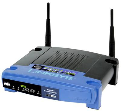
    Power on all of the computers on the network. If any of the systems doesn't have a wireless card already, insert a USB wireless adapter and install the software off of the included CD. Once all of the computers are wireless-ready, plug in the power to the wireless router. The lights on the front should come on. To connect your cable or DSL modem to the router, plug the modem's networking cable into the port labeled "LAN" or "Internet" on the back of the router. Wait a minute for the router to fully start and initialize before moving on to the next step.
  • Step 2
    Double-click on the wireless icon in the lower-right corner of the screen. The default icon used by Windows looks like an antenna, though if you have third-party software installed, the icon may be the logo of the wireless card manufacturer instead. If unsure, hover your mouse over the icon and read the description text that pops up before clicking.
  • Step 3
    Look through the list of available wireless networks. It may take up to fifteen seconds for the list to appear, so be patient as the tool searches for open connections. Your router's name will likely correspond to the brand or model of the router, so you should easily recognize it. It will usually also be the strongest signal on the list of available networks. Double-click on it to connect. It may take up to 90 seconds for the connection to be completed.
  • Step 4
    Open up your web browser and test your connection by visiting any site on the internet. The network is now fully installed. If you wish to enable the security features of the wireless router, such as WPA encryption and password-protection, consult your router's documentation. Every brand uses a different system, so configuration methods will vary from one model to the next.

How to Use an USB G or G+ wireless network adapter card with Windows Vista

Learn how to install and use an USB wireless network adapter card to surf the internet.

  • Step 1
    Many wireless cards say they may not work with Vista, they usually will work however if you follow these steps. Step One: Plug in your USB Network Adapter to any USB port on your computer.
  • Step 2
    After plugging in your USB Network card, Follow the New Hardware Installation wizard that should pop up in Vista. If you have used the wizard already with no success, don't worry. Just skip this step, it is not necessary.
  • Step 3
    Go to your start menu and right click "My Computer", from the drop-down menu choose "Manage".
  • Step 4
    In the manage window, on the right click "Device Manager". On the left you should see a list of devices known to your computer.
  • Step 5
    Under the tab "Network Devices" you should see a yellow icon next to "wireless USB device" This indicated the device you plugged in has not been configured properly.
  • Step 6
    Right click the "Wireless USB Device" you are trying to install and choose "Update Driver Software" from the drop down menu. This will bring up another box with two options.
  • Step 7
    Click the second option which is "Browse my computer for software". On the next screen, if you have the CD that came with your wireless card, type "D:" into the location field and select the box under that field that says "Include sub folders". If you do not have the Driver CD skip to the next step.
  • Step 8
    If you don't have the CD with drivers on it find the name and model of your wireless card (its on the back of the card, do not mistake the MAC address for the model number, you won't need the MAC address right now). Go to the manufacturers website which you can find in any search engine, and look for a place to download the drivers. Download drivers into any folder you wish and repeat step 7, except instead of typing "D:" type the location of the folder where you downloaded the drivers. For example "C:\Windows\USERNAME\downloads".
  • Step 9
    After you are able to install the drivers, you should be able to verify the card is working by going back to Device Manager (as described in steps 3 & 4) and looking in your "Network Adapters". If there is no yellow icon next your USB network device, you have installed this device correctly. Further verify correct installation by right clicking your device in the device manager and choosing "Properties", you should see a statement that "this device is working".
  • Step 10
    Now the device is installed and ready to use. It will probably be blinking with a green LED depending on the model

check your IP configuration in windows


  • Step 1
    Click START

  • Step 2
    Click RUN

  • Step 3
    Type CMD

  • Step 4
    In prompt windows, Type IPCONFIG

About Ethernet Frames

Ethernet technology is based on the idea of computers communicating with one another over a shared network. For the layered communication in computer network protocol, ethernet is the backbone. An ethernet network works by broadcasting signals in the form of action and protocol information by using a common signal address. Several different ethernet frame types are used to broadcast information using individual packets of data. Ethernet stations communicate with the individual computers and other ethernet stations in order to create a shared network of information. In some ways, the ethernet frames communicate similarly to the way radio broadcasts function.

    History

  1. Research on ethernet framing systems began in 1972 at Xerox. The first version that was developed, referred to as Ethernet Version 1, was released just 8 years later by the DIX consortium, which was comprised of Xerox, Intel and DEC. Robert Metcalfe, David Boggs, Chuck Thacker and Butler Lampson were the inventors credited with the invention of Version 1. In 1980, the same year the first version was released, research began on a newer version of ethernet frame. The new frame, Version II Ethernet, was released in 1982. The following year, Novell NetWare '86 was released, which was based on the specifications used in Version 1. In 1985, Novell's final version, the 802.3 was released. This version had been modified for compatibility. A final ethernet frame was developed shortly after Novell's propriety that was created to address the compatibility issues between Version 2 and 802.3.
  2. Types

  3. There are four main ethernet frame format types currently available for commercial use. While the digital signal coding for an ethernet network is always the same, the ethernet frames are substantially different from one another. Each frame type has a different measure of Maximum Transmission Unit (MTU)--the value of the communication packet it has the ability to send--but each can coexist on the same physical ethernet network. The four main frame types are IEEE 802.3 or Version 1, Ethernet Version II, IEEE 802.2 LLC Frame and IEEE 802.2 Snap Frame. The most popular and most often used ethernet frame is Version II, also referred to as the DIX frame. Version 1 has all but fallen to the wayside since the launch of Version II. The IEEE 802.3 from Novell is a non-standard variation of the original version from DIX and IEEE 802.2 was created to help compatibility flaws between Version II and 802.3. It important to note that different companies, like Cisco and Novell, have different names for each frame type.
  4. Significance

  5. Ethernet changed the face of computer technology and the speed at which business and personal information is exchanged. Just 30 years ago it was impossible for diversified companies with offices on both coasts to share information instantaneously over a shared network, but ethernet allows for reliable access to this information. In our technology revolution and the current rate at which new technologies are conceived, it is a significant feat that the original ethernet has changed very little since its inception almost 30 years ago. While the ethernet frame types have made some advancements, like the switch from a coaxial cable to point-to-point links, the basic model of an ethernet frame on a physical level has changed very little.
  6. Benefits

  7. Because ethernet frames are a versatile technology they are very popular for linking network systems. The perceived benefits are that most information in a network system begins and ends inside an ethernet frame. These end-to-end frame types have unique destination sources and addresses, which gives a certain sense of security to ethernet customers. The four framing types are compatible with all types of protocol packets and can thus work with any networking system. Another benefit of ethernet and ethernet framing types are that additional networking features can be added to the system as easily as any IP network system.
  8. Potential

  9. Since the first ethernet frame type was developed in 1980, the advancements in ethernet have grown exponentially. Instead of being a separate piece of technology, ethernet has become a part of the standard computer. Because of the necessity of ethernet today, most companies have switched from building separate ethernet cards that attach externally to a computer. Computers are now built with ethernet technology directly into the motherboard. Ethernet will only continue to get faster. Gigabit Ethernet will soon be replaced by Terabit Ethernet, which will increase the speed of ethernet technology by 100 times what it is today and hardware designers have already developed testing models that can transmit these new, much faster, signals.

Color Code for an Ethernet Cable

Ethernet cables are cables used specifically for the ethernet protocol. The most common cable type used for ethernet applications is category 5 (Cat5), a shielded cable that contains four pairs of twisted wires. Cat5 cables are more popular for ethernet applications than other options, such as coaxial cables, because of their high transfer speed over short distances.

    Identification

  1. Ethernet Cable Pin Diagram
    The pins on the connector should be read left (1) to right (8), with the connector held vertically and the contacts facing you.
  2. Pins 1 and 2

  3. The green striped wire connects to pin 1. The solid green connects to pin 2. This pair receives data.
  4. Pins 3 and 4

  5. The orange striped wire connects to pin 3. The solid blue connects to pin 4. The orange striped wire transmits data, while the blue is unused.
  6. Pins 5 and 6

  7. The blue striped wire connects to pin 5. The solid orange connects to pin 6. The orange wire transmits data, and and the blue wire is unused.
  8. Pins 7 and 8

  9. The brown striped wire connects to pin 7. The solid brown connects to pin 8. This pair is not used.

About Ethernet Cables

Ethernet cables are the physical lines of communication between two devices on an Ethernet network. All home networks and most business networks are Ethernet based. The vast majority of Ethernet cables are copper twisted-pair, but there are different types, categories, grades and uses of Ethernet cables.

Identification

  1. Ethernet is a network architecture defined by the Institute of Electrical and Electronics Engineers (IEEE) 802.3 standard. They also define the types of cables.
  2. Types

  3. Ethernet cables can be either fiber optic (glass or plastic) or copper (twisted-pair or coax).
  4. Copper Wire

  5. Old Ethernet cables were copper coax, similar to cable TV. Almost all cables now are four pair twisted-pair, similar to telephone cables. Copper, which is cheap, is used for short (less than 100m) runs from central devices to end devices.
  6. Fiber Optic Cables

  7. Fiber optic Ethernet cables are microscopic strands of glass or plastic that use light to send data. Fiber is expensive, requires special handling, and is therefore used for long distance (as far as 2km).
  8. Cable Ends


  1. Twisted-pair Ethernet cables are terminated on eight position, eight contact connectors based on the TIA/EIA 568 standard. TIA/EIA 568A is for home networks; TIA/EIA 568B is for business networks.
  2. Speed

  3. Copper twisted-pair works at speeds up to one Gigabit per second (1 Gbps). Fiber optic speeds can exceed 10 Gbps.

How to Tell If Computer Has an Ethernet Card?

An ethernet card, also known as an ethernet PCI adapter, is a type of network interface adapter found inside most new desktop computers and laptops. An ethernet card allows computer users to plug an ethernet cable into the card in order to connect to a wired high-speed network. Knowing how to tell if your computer has an ethernet card will help you determine if you can connect your computer to a wired high-speed network or if you must separately purchase and install an ethernet card for your computer before you can access wired high-speed networks.

  • Step 1
    Identify all ports and jacks on your computer. To tell if your computer has an ethernet card, you can look for an ethernet jack on your computer's back panel. To do this, though, you must be able to tell the difference between an ethernet jack and the other ports and jacks on the back of your computer. The ethernet jack is shaped similar to a telephone jack and will have an LED light next to the jack. Your computer may also label the jack with the word "Ethernet" or "Ether" directly above the jack.
  • Step 2
    Distinguish the ethernet jack from the modem jack. If your computer does not have labels on its ports/jacks and your computer is equipped with a modem, you may have difficulty distinguishing between the modem jack and the ethernet jack. Both jacks are shaped similarly, but the ethernet jack is wider and shaped more like a rectangle. The modem jack is smaller and square-shaped. If your computer does not have labels on its port but uses symbols instead, you can distinguish between the ethernet jack and the modem jack by seeing which jack has a telephone symbol above it. This will be the modem jack. If your computer has only one jack and it is square-shaped as opposed to rectangular, your computer does not have an ethernet card.
  • Step 3
    Find the ethernet PCI card from inside the computer. You can tell if your computer has an ethernet card by looking at the internal hardware of your computer. First, power off and unplug your computer. Using a Phillips screwdriver, unscrew and remove the outer case of your computer. Locate your computer's motherboard and examine all of the PCI cards that are in its PCI bus slots. If your computer is equipped with an ethernet card, you will find a rectangular-shaped PCI card that has a large black or gray box at the connector end of the PCI card. This box is where the ethernet cable is to be plugged into your computer. If you do not see a PCI card like this, your computer does not have an ethernet card.
  • Step 4
    Use your operating system to check for an ethernet card. Another way you can determine if your computer has an Ethernet card is to see if a network adapter is in your operating system's list of hardware devices. In Windows, do this by accessing the "Device Manager." Right-click the "My Computer" icon on your PC, then click "Properties." Select the "Hardware" tab in the "System Properties" dialog box that appears, then select "Device Manager." Scroll down the list of devices until you see the "Network Adapters" heading. Click the "+" symbol next to "Network Adapters" to expand the list to see if it lists an ethernet adapter. If no device is listed, your PC does not have an ethernet card. In Mac OS X, search for a network adapter by opening the "Apple" menu, then clicking "System Preferences," "View," then "Network." When the "Show" menu loads, click "Active Network Ports" to see if your Mac lists an ethernet card. If it does not, the computer does not have an ethernet card.

Wireless Router Work With Dial-Up

    Necessary Hardware

  1. To transmit your dial-up Internet connection as a wireless signal, you will need to first run the telephone line into a modem, then to a wired broadband router and finally to a wireless transmitter. Please note that your wireless router will need to feature RS-232 serial ports to be compatible with an external modem; additionally, any computers wishing to connect to the wireless network will need to have the appropriate wireless cards installed. Lastly, in addition to the above, you will also want to have two Ethernet cables and a surge protector/power strip to protect your electronic equipment.
  2. Connecting to the Modem

  3. Take your telephone line from the wall and connect it to your external modem, which you will plug into your surge protector. Connect your first Ethernet cable to the output on your external modem.
  4. Connecting The Modem To The Wired Router

  5. Take your Ethernet cord that leads from your external modem and connect it to the input on your wired router. Again, for your router to be compatible with a dial-up modem, you must have a router with RS-232 serial ports. Connect your second Ethernet cable to the wired router's output.
  6. Connecting To The Wireless Router

  7. Connect the Ethernet cable from the wired router to the wireless router's input. Connect both the wired and wireless routers to your surge protector. Once you have connected all of your hardware and installed any applicable software (which would be included with your hardware), you are ready to connect wirelessly to the Internet via your dial up connection!

Wireless Ethernet Cards

A wireless Ethernet card is used to connect any networking device (such as a laptop or PDA) to a wireless Ethernet network. Also known as a Network Interface Card or NIC, a wireless card enables computing mobility, essential to taking advantage of the increasingly sophisticated development of emerging mobile tools and applications. Unless otherwise stated, wireless Ethernet cards are built into computing devices and are about 100 times faster than standard Internet modems.


    Function

  1. Wireless Ethernet cards use radio waves to transmit data. This is different than DSL (digital subscriber line) or cable Internet connections, which transmit data via a hard-wire phone line.
  2. Features

  3. Although wireless cards and networks rely on radio waves, the communication is done at higher frequencies than cell phones or radios (2.4 or 5.0 GHz) and at three different frequencies; allowing wireless cards to handle more data.
  4. Signal

  5. Under normal conditions, the signals of wireless Ethernet cards and networks typically travel 75 to 150 feet. Though they're stronger than regular radio signals, they are still vulnerable to the interference caused by physical obstructions.
  6. Considerations

  7. Communication and data transferred across a wireless network is easier to intercept by hackers and eavesdroppers than transfers over hard-wired networks.
  8. Fun Fact

  9. According to the Wi-Fi Alliance, perfect conditions (wide open areas, no obstacles) have shown that wireless signals can transmit data up to 1,000 feet and have even been documented to reach 1 mile.

Install an Ethernet Card

To connect to the Internet through a cable or broadband modem, your Dell desktop computer will have to have a device called an Ethernet card, which is also known as a network interface card. If your desktop for some reason does not have one, or the current one is defective, you can install one on your own by opening up the case and accessing the computer's motherboard

  • Step 1
    Choose the option in the "Start" menu to shut down your Dell desktop computer. Remove all of the cables and cords from the back of the computer and then set it on its side on a stable work surface.
  • Step 2
    Check along the left side of the computer case to see if it has any screws, if there is a large depression in the middle of the case, or if there is a metal tab where the side panel meets with the back metal panel.
  • Step 3
    Push down on the depression in the case if it has one and then slide it back to remove the side panel. Pull the metal tab, if one is present, directly away from the case and then pull the side panel toward you to remove it. Use a screwdriver to pull out all four screws along the side of the case and then pull the side panel off if the computer has screws instead.
  • Step 4
    Find the PCI card slot on the bottom left corner of the motherboard. Pop out the plastic cover over the card slot with your fingers and then remove the two screws attached to the case.
  • Step 5
    Check the notches on the bottom of the Ethernet card and then press the card down into the slot in the correct direction. Connect the screws back into the case to hold the card in place.
  • Step 6
    Slide the panel back onto the case and then reconnect the case screws if there were any. Plug the cables into the ports on the back of the computer and turn it back on. Navigate your web browser to the Ethernet card manufacturer's website and check to see if it has an updated driver to download, or instead put the installation CD that came with the card into your computer. Follow the on-screen instructions to finish the installation.

Install a Network Card

You will learn how to hold a network card, remove the cover on the tower, how to remove a network card, how to install a network card, how to replace the cover to the tower, and how to install the drivers for the network card onto the computer.
  • Step 1
    Start by disconnecting any cables that are connected to the tower.
  • Step 2
    Remove the cover to the tower by taking out the screws holding it in place.
  • Step 3
    Remove the screw that's holding the card in place if there's already one in the slot.
  • Step 4
    Carefully pull out the card without touching the top or bottom of the card.
  • Step 5
    open the box to the new card and carefully insert it into the slot and place the screws back in to hold it into place.
  • Step 6
    Replace the cover and connect all the cords to the tower, then start the computer.
  • Step 7
    Insert the drivers disk into your tower and follow the step by step directions to install the drivers.

How Does a Network Hub Work?

Function

  1. A network hub is a networking device that connects to one or more equipment. For example, a computer can connect to a server, printer and another computer through a network hub. It is useful in sharing of resources and broadcasting data it receives. It helps connects these devices together without having to connect to each other directly. There are three types of network hubs: Passive Hubs, Active Hubs and Intelligent Hubs.
  2. Passive Hubs

  3. One of the types of a network hub is the so-called passive hub. It's a pass-through that does not do anything more than just broadcast signals it receives through its input port, then sends it out through the output port. It does not do anything to regenerate or process the signals because it only functions as a connector of different wires in a topology.
  4. Active Hubs

  5. An active hub works more than just a connector but also regenerates the data bits to ensure the signals are strong. Another name for an active hub is a multiport repeater. It provides an active participation in the network aside from acting as an interface. It participates in the data communication, such as storing signals received through the input ports, before forwarding them. It can monitor the data it is forwarding and sometimes help improve signals before forwarding them to other connections. Such a feature makes troubleshooting of network problems easier.
  6. Intelligent Hubs

  7. An intelligent hub can perform everything that the passive hub and active hub do, and help manage the network resources effectively to ensure that the performance of the network is highly efficient. An intelligent hub can help in troubleshooting by pinpointing the actual location of the problem and help identify the root cause and resolution. It is very adaptable to different technologies without any need to change its configuration. The intelligent hub performs different functions such as bridging, routing, switching and network management.
  8. Speeds

  9. Network hubs come in different speeds, also known as network data rate or bandwidth. There are older network hubs that offer 10 Mbps speeds, then later in 100 Mbps. In bigger networks, it may be necessary to use a dual speed network hub, which comes in both 10 and 100 Mbps in order to provide connection points for computers or printers that are running 10/100 Mbps.

    In a home office or small business, one can use a smaller network hub that usually comes in four or six ports. Before buying a hub, take into consideration how much equipment needs to connect to the network hub.
  10. Setting Up a Network Hub at Home

  11. Get an Internet connection from an ISP (Internet Service Provider). After your Internet connection is installed, you can connect your network hub into the modem by using a network cable (Cat5 or RJ-45). Then you can connect one more cable to the NIC (Network Interface Card) of your computer; doing the same with other computers or printers that need to be in your network. If you have a wireless network, you can get a wireless hub; just make sure your hub has enough number of wireless ports available for every connection.

Difference Between a Router & Hub

he terms "hub and "router" are often used interchangeably, and although they have some similarities, there are definite differences between the two devices. It is important to know what the differences between the two are, particularly if you need to shop for either a hub or a router.

    Types

  1. A hub and router are both networking devices designed to link two or more computers and networks to each other. Both devices feature multiple ports in the front or back, which provide connection points between computers and networks. The key distinguishing feature is the way each functions to handle network traffic.

Hubs

A hub is designed to serve as a shared connection point that links two or more devices in a network. Typically, it is used to link separate segments of a LAN, enabling them to act as a single segment. When a packet of data arrives at one of a hub's ports, it is forwarded to every single port without distinguishing where it actually needs to go. Today, hubs are becoming obsolete as inexpensive network switches are becoming increasingly rare.

Routers

  1. A router is a "smarter," more sophisticated hardware device. It is designed to link multiple networks such as local area networks (LANs), or a wide area networks (WANs). A router is typically connected to at least two networks via a gateway, directing the flow of data packets within and between networks.
  2. Function

  3. A router serves as a default, intermediary destination for the traffic in the network. Some specialized routers are specifically designed to link different types of networks. Broadband routers, for example, are designed to enable a LAN to connect to the Internet, or to a WAN for Internet connection sharing. A hub is not capable of linking multiple networks or sharing an Internet connection. In home networking, network hubs are primarily used for wired networks, while routers can be used for both wired and wireless networks.
  4. Significance

  5. A router has a more intricate and involved operation than a hub. When data arrives at the router, rather than forward the data packets to all of its ports as a hub would, a router filters and directs (routes) network traffic to the appropriate ports. In a corporate network, for example, a router typically receives TCP/IP packets, which it analyzes to determine the identifying IP addresses. These packets are then forwarded to their final intended destinations.
    The router uses headers and forwarding tables to determine which is the best method for forwarding the data packets. If more than one router is involved, protocols are used to communicate with each other and configure the best router that needs to be used.

What is a Network Hub Used For?

A network hub is a piece of computer hardware used to connect multiple computers to each other. It is most often used in a small Local Area Network (LAN) setting where there is little need to prevent traffic conflicts. Network hubs are generally considered the cheapest and easiest way to connect several computers so that they can share resources like Internet connections.

    Appearance

  1. A network hub is most often a small, nearly flat, plastic box. The network hub has 4, 5, 8 or 16 ports on the back and LED display lights on the front. It is powered by a regular household electricity from an adapter cord.
  2. Function

  3. The network hub receives data packets from each of the computers connected to the hub and transmits them to all other computers that are connected to the network.
  4. Types of Network Hubs

  5. There are three basic types of network hubs. Passive hubs receive and transmit data. Active hubs receive data and transmit it with amplification to strengthen the signal. Intelligent hubs also include processing functions so that they can manage and monitor traffic on the network.
  6. Advantages of Network Hubs

  7. A network hub allows two or more computers to access and share resources on any of the other computers on the same network. An intelligent network hub can provide the ability to monitor traffic and use of the network. Network hubs are less expensive than routers and switches.
  8. Drawbacks of Network Hubs

  9. Computers connected through a network hub may suffer from slower network speeds or disconnection if one computer is using a greater amount of bandwidth.

What is a Network Hub?

A network hub is the actual hardware or device that allows multiple computers to connect together forming a network. A network hub is a critical component for allowing more than one computer to connect with other computers. Network hubs are common in home offices and businesses.

    Function

  1. A hub is a network device where the information flow is accumulated and then distributed to various groups and users. It can be used between the users on the same Local Area Network (LAN) and users on different LAN. A hub is one of the most essential components in a network. Hubs are devices that serve as the central point where cables from all nodes come together.
  2. Features

  3. Computers are connected together for many purposes like sharing resources and workload, communication and reliability. A network hub is a device that is used to connect multiple Ethernet devices together. The devices being connected should be using twisted pair or fiber optic cables for connection. Once the devices are connected, they become a part of the network. A hub has multiple ports into which the many cables go. All the cables that go into the hub are interconnected.
  4. Significance

  5. The hub is a device that works at the physical layer of the OSI model. This is because it deals with the actual physical transmission: the way signals are converted and carried on through physical media. A hub also acts as a repeater. When being transmitted in the form of electromagnetic waves, signals become weak with distance. A repeater hub will amplify and regenerate the signal for better quality and life. By using repeater hubs, the distance can be extended.
  6. Size

  7. Hubs are available in all shapes and sizes. There are hubs which simply pass on the signals from one node to another. These are called dumb hubs. Then there are smart hubs that come with some limited management capabilities also. There are also available some intelligent hubs. These hubs can support multiple LANs and topologies and can provide extensive management capabilities. These hubs can even house other module types such as routers and bridges.
  8. Types

  9. If you are using an Ethernet LAN but need to go farther than usual, just add a repeater to achieve the added distance. These types of hubs which do let the signal vanish are called active hubs. These are also called multi port repeaters. If they do not work as a repeater they are known as passive hubs.
  10. Identification

  11. Hubs generally have four to twenty four RJ-45 ports for twisted pair cabling and one or more uplink ports for connecting the hub to other hubs. Hubs have indicator lights to indicate the port link status and status of collisions.